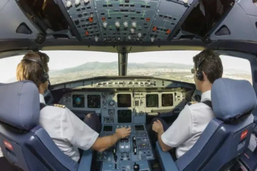
Fly-by-Wire (FBW), often referred to as FBW, stands as the widely accepted term for flight control systems utilizing computers to process the inputs from the pilot or autopilot. These processed inputs are then translated into corresponding electrical signals directing the flight control surface actuators. This modern setup replaces traditional mechanical linkage, ensuring that the pilot’s inputs no longer directly manipulate the control surfaces. Instead, a computer interprets the inputs and moves the control surfaces accordingly, aligning with the active Flight Control Laws.
Why It’s Beneficial
The advantages of Fly-by-Wire technology are profound, originating in military aircraft design. Initially embraced for military applications, where weight reduction, heightened reliability, damage tolerance, and precise control for maneuverable aircraft were crucial. The F-16, introduced in 1973, became the pioneer by implementing FBW for all flight controls, abandoning traditional mechanical or hydraulically-assisted methods. In the realm of military fast jets, where agility is paramount, FBW offers the ability to swiftly detect and automatically rectify unintended deviations in angle of attack or sideslip. This proactive correction, initiated while the issue is minor, significantly contributes to safety. Moreover, FBW facilitates robust flight envelope protection systems, enhancing safety when the FBW system operates at its standard level.
How It Operates
The underlying principle of Fly-by-Wire involves error control, where the flight control computer (FCC) continuously monitors and adjusts the position of a control surface based on the input signals. When a pilot or autopilot command is initiated, the computer analyzes the variance between the current and desired control surface positions. The FCC then sends an electrically generated corrective signal to the control surface, aligning it with the intended position. This continuous feedback loop ensures that any disparity between the desired and actual positions prompts corrective action.
In the FBW system, the signal route from FCC to control surface is termed the “forward path,” while the route from the control surface to the FCC is known as the “feedback loop.” Gain, representing amplification or attenuation, modulates the forward signal to achieve the desired aircraft response. To maintain efficiency, a filter may be employed to block signals or motion feedback occurring too frequently.
The strength of a feedback system lies in its capacity to reduce sensitivity to alterations in the aircraft’s stability characteristics or external disturbances. Autopilots, stability augmentation systems (SAS), and control augmentation systems (CAS) all operate as feedback control systems within the flight control system (FCS).
In a SAS, a damper function is included in the feedback loop, typically with low control surface influence. Meanwhile, a CAS takes its place in the forward path, akin to high-authority “power steering,” delivering consistent responses across diverse flight conditions. Previously employed independently in military aircraft, the CAS and SAS principles, when integrated into an FCS, offer enhanced precision and flexibility. This synergy ensures a dependable aircraft response across a wide flight envelope, adjusting CAS gains based on factors such as airspeed, Mach number, center-of-gravity position, and configuration.
Control Laws
At the core of an FCS, the FCCs are programmed with control laws dictating the feedback control system. Control laws usually bear names reflecting the primary feedback parameter, like “xxx feedback” or “xxx command.” Common feedbacks encompass:
- Pitch Channel: involving vertical load factor “g,” pitch rate “q,” pitch angle “θ,” and angle of attack “α.”
- Roll Channel: entailing bank angle “φ” and roll rate “p.”
- Yaw Channel: covering yaw rate “r,” sideslip angle “β,” and rate of change of sideslip angle “β̇” (pronounced beta dot).
In a “G command” system, desirable for high speeds, applying a specific control column force yields the same “g” regardless of prevailing airspeed. Similarly, a pitch-rate command system ensures a consistent pitch rate for a given control column force, irrespective of airspeed.
To balance rapid communication of pilot commands with maintaining a contextual basis for precision, the FCC establishes a direct path to the elevator through the “proportional line” or “feed forward gain.” Simultaneously, the same command undergoes a parallel circuit “integrator,” generating a control surface command until the feedback signal aligns with the pilot’s original command. Engineers must fine-tune the integrator gain setting to prevent excessive lag.
A “proportional plus integral” control, combining the proportional line and integrator, is a common feature in most fly-by-wire designs, embraced by both Boeing and Airbus. Excessive lag, akin to the known human performance delay termed pilot-induced oscillation (PIO), is mitigated by this balanced arrangement in an FCS, preventing delays in directional changes like transitioning from nose-up to nose-down.
In an aircraft employing pitch-rate command or g command for pitch control, attaining attitude hold with free controls is akin to the control wheel steering (CWS) function of an autopilot. When you adjust the pitch attitude and release control pressure at the desired attitude, the system maintains that new attitude by reacting to bring pitch rate to zero. Flying the aircraft should require only moderate control forces, ensuring precise attitude control. An additional advantage of pitch-rate or g feedback is auto trim, allowing speed, thrust, or configuration changes without needing re-trimming for level flight. Auto trim contributes to apparent neutral-speed stability, though some FBW types retain a semblance of conventional trim “feel.”
A widely used control law combining g and pitch-rate feedback is known as C* (pronounced C star). At low speeds, a C* airplane relies on pitch rate, while at higher speeds, g becomes the dominant factor. The transition, occurring around 210 knots in Airbus A320 series aircraft, is seamless. Boeing incorporates a modified C* control law, C*U, where “U” represents aircraft forward speed, providing apparent speed stability. This system allows the pilot to “trim a speed” rather than the pitch control surface, offering tactile high-speed cues as the pilot approaches the maximum trim reference speed of 330 knots.
Exploring specific flight phases in more detail, FBW permits designers to optimize effective dynamics for different phases, introducing modes like approach or flare mode, creating a versatile multi-mode FCS.
In both the Airbus A320 series and the Boeing 777, control laws become fully active post-takeoff due to the sensors’ sensitivity to vibration during the takeoff roll. Landing requires additional transitions. Considering ground effect as a unique factor in landing, the control law may need “flare compensation” to ensure the customary rearward control column movement for a successful flare. For instance, in the Boeing 777’s C* control law, an artificial nose-down pitch command is introduced at 30 feet radio altitude for this purpose. Boeing 777 control laws have been refined during flight tests to enhance de-rotation characteristics compared to the Boeing 757 and 767. More details on Airbus and Boeing control laws can be found in the separate article Flight Control Laws.
System Redundancy
Rather than offering a conventional FCS for backup, the typical approach for commercial aircraft wholly controlled by FBW is redundancy, achieved by installing additional FCCs and sensors. Civil airliners with FBW generally feature triplex FCSs, as seen in the Boeing 777 and Airbus A340. These aircraft also include limited mechanical backup to ensure survivability during cruise, allowing resolution of any electrical issues. Duplex FBW systems are expected to incorporate full mechanical backup when all components are operational. In the FCS operates in normal law. Limited failures prompt auto reversion to a degraded FCS mode, with the lowest backup mode being Direct Law. In Direct Law, there is no feedback control, and fixed gains may be employed for acceptable control forces proportional to control surface deflection, potentially optimized for specific configurations such as landing.
Feedback control, essential for maintaining airspeed, Mach number, attitude, and angle of attack within the certificated flight envelope of an FBW aircraft, can be executed through two main strategies. Airbus employs the “hard limits” strategy, where control laws hold absolute authority unless the pilot opts for Direct Law. Conversely, Boeing adopts “soft limits,” allowing pilots to override Flight Envelope Protection, retaining ultimate control over the aircraft’s operation.
Accidents and Incidents
Several incidents have involved flight envelope protection:
- On 27 February 2012, an Airbus A330 encountered severe turbulence due to crew failure to use weather radar properly. Flight envelope protection activation and subsequent crew action were appropriate.
- On 24 March 2012, an Air France Airbus A319 descended rapidly toward Tunis with excessive speed and a non-stabilized approach. Investigation cited sloppy CRM and lack of awareness of automation.
- On 3 April 2012, an Air France Airbus A320 crew faced challenges during an RNAV VISUAL approach at Tel Aviv. The investigation identified issues with crew understanding of automation, FMS modes, and inadequate procedures and training.
- On 15 September 2012, a Learjet 24 suffered double engine failure and a stall during base leg positioning, leading to terrain impact. Investigation revealed fuel starvation and mismanagement of the fuel system.
- On 9 February 2014, a military Airbus A330 experienced an upset in cruise due to the Captain’s seat movement, activating the Flight Envelope Protection System for recovery.
- On 5 November 2014, an Airbus A321 temporarily lost control due to blocked AOA probes, activating high AOA protection.
- On 19 August 2017, an Airbus A340-300 faced unexpected windshear during takeoff from Bogotá, triggering angle of attack flight envelope protection. Investigation revealed the absence of a windshear detection system and communication issues from ATC, leading to operational changes at the airport.
- On 27 November 2017, an Embraer EMB 550 crew ignored a pre-takeoff indication of an inoperative airframe ice protection system. The flight ended in a runway impact due to mismanagement of flight envelope protection during approach.
These incidents underscore the significance of understanding and effectively managing flight envelope protection systems.


