Instrument flying demands precision, and nowhere is that more evident than during a non-precision approach. While modern navigation systems have brought vertical guidance to many procedures, pilots still face the challenge of manually managing descent rates when such guidance is absent. Understanding how to calculate your descent rate to Minimum Descent Altitude (MDA) is crucial for maintaining obstacle clearance, ensuring a stable approach, and avoiding rushed or dangerous decisions near the runway.
The Unique Challenge of Non-Precision Approaches
On a non-precision approach, the lack of a glidepath means it’s up to the pilot to determine where and how quickly to descend. Misjudging the descent can lead to arriving at the MDA too early or too late, both of which reduce safety margins. Descending too slowly risks reaching the missed approach point (MAP) still above MDA. Conversely, descending too rapidly can result in an unstabilized approach, compromising situational awareness and aircraft control.
The traditional method of “dive and drive” — rapidly descending to MDA and flying level — is discouraged in modern training. Instead, we aim for constant descent final approaches (CDFA), which mirror the stable glidepaths of precision approaches, ensuring a smoother and safer experience.
Applying the 1 in 60 Rule to Calculate Descent Angles
To effectively plan a descent to MDA, we employ the “1 in 60 Rule,” a tried-and-tested tool in aviation navigation. This rule states that a 1° change in pitch equals approximately 100 feet per nautical mile (NM) of vertical change. It’s a simple yet powerful way to derive descent angles without relying on vertical guidance.
For example, if you need to descend 400 feet over 4 NM, you divide 400 by 4, resulting in a required descent of 100 feet per NM. According to the 1 in 60 Rule, this equals a 1° pitch change.
This methodology allows pilots to plan a descent angle that gets them to the MDA exactly at the FAF or just prior to the MAP, depending on the profile. It promotes a consistent vertical path and ensures that altitude restrictions are met without unnecessary level-offs.
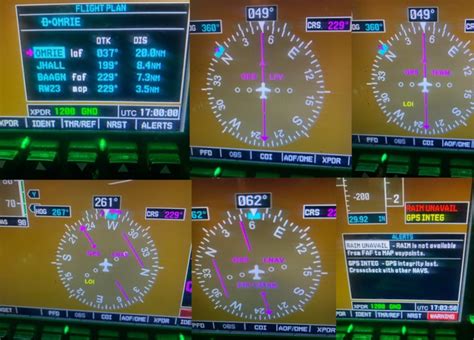
Estimating Pitch in Glass and Analog Cockpits
While the theory is straightforward, practically applying a 1° pitch change can vary depending on your aircraft’s avionics. In a glass cockpit, pitch indications are typically clearer, with markings at regular intervals (0°, -2.5°, -5°, etc.). Thus, estimating a 1° descent becomes manageable.
In a round-dial aircraft, estimating 1° is more art than science due to the smaller pitch scales. Pilots often rely on visual approximations and, when available, vertical speed indicators (VSI) to back up their pitch angle with a descent rate in feet per minute (FPM).
Converting Descent Angle to VSI Rate
To make life easier in turbulence or variable conditions, converting pitch to a VSI target helps maintain vertical profile stability. Use the formula:
Descent Rate (FPM) = Descent Angle × Miles Per Minute × 100
Let’s apply this with an example:
- Aircraft Speed: 120 knots
- Groundspeed Conversion: 120 ÷ 60 = 2 NM per minute
- Descent Angle: 1°
- FPM Descent: 1 × 2 × 100 = 200 FPM
At 90 knots, the same angle gives:
- 90 ÷ 60 = 1.5 NM/min
- 1 × 1.5 × 100 = 150 FPM
These manageable descent rates facilitate a controlled, gradual descent — crucial during IMC when external visual references are unavailable.
Real-World Example: RNAV Approach to Runway 12L
Consider an RNAV approach with multiple descent segments. From the Intermediate Fix (IF) HALFF to PYYPP (Final Approach Fix, FAF), the descent is from 7,100′ to 6,700′ — a 400-foot loss over 4 NM. As previously calculated, that’s 100 feet per NM or a 1° descent.
At 120 knots, you’d aim for a 200 FPM descent. It’s a modest rate, which offers flexibility but demands close monitoring due to possible distractions or weather deviations.
Beyond PYYPP, the descent angle steepens to 3° down to the runway threshold at 41 feet AGL. Now the calculation changes:
- 3 × 2 NM/min × 100 = 600 FPM at 120 knots
This highlights how different approach segments may require adjustments in pitch or descent rate. Not anticipating this can leave you either too high or too steep at a critical phase.
What If the Descent Angle Isn’t Published?
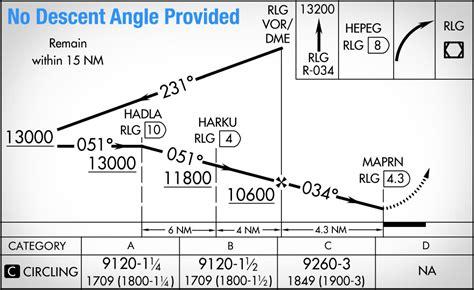
Not all approaches offer descent angles. In such cases, you’ll need to do some quick mental math or plan ahead. Take the VOR-DME-A into Kremmling, CO (20V):
From FAF (RLG VOR) at 10,600 feet to MAPRN at 9,120 feet, there’s a 1,480-foot descent over 4.3 NM.
Rounded to 4 NM:
- 1,480 ÷ 4 = 370 FPNM (feet per nautical mile)
- 370 ÷ 100 = 3.7° pitch
Rounded up to a practical 4° descent, you then calculate VSI:
- 4 × 2 (at 120 knots) × 100 = 800 FPM
- At 90 knots: 4 × 1.5 × 100 = 600 FPM
Knowing this in advance lets you brief the approach with precision, decide on configuration timing, and ensures you’re not diving too steeply near MDA.
Maintaining a Stabilized Approach to MDA
A critical part of descent planning is ensuring the aircraft remains in a stabilized flight path, especially when descending to MDA without visual references. An unstabilized descent — characterized by fluctuating speeds, pitch changes, or power settings — can jeopardize the approach.
Using calculated descent angles and matching VSI targets helps enforce stability. Ideally, your approach configuration (gear, flaps, power) is set prior to the FAF so that pitch and power changes remain minimal throughout the descent.
Even if visibility improves below MDA, a rushed or unstable profile can result in a go-around, negating all previous planning.
From MDA to the Runway: Visual Segment Considerations
Once you’ve reached MDA, descent below it is only authorized when required visual references are in sight. From that point, you must continue the descent at a rate that maintains a stable path to landing.
On some approach plates, the visual segment is shaded (often gray), indicating it’s clear of obstacles, provided descent occurs at or above the published glide slope (typically 34:1). In our RNAV 12L example, the segment from DUUUD to the runway is such a case.
This segment requires visual confirmation but assumes that the terrain has been analyzed. Still, rushing below MDA without positive contact with runway environment risks controlled flight into terrain (CFIT).
When Precision Isn’t Available, Precision Is Still Expected
Non-precision approaches, by definition, lack electronic glidepath guidance — but that doesn’t excuse sloppy flying. By employing a systematic method using the 1 in 60 Rule, converting angles to descent rates, and maintaining a disciplined, stable profile, pilots can fly these approaches with the same care as a precision approach.
This calculated approach reduces workload, enhances situational awareness, and ensures greater safety margins, particularly in challenging environments like mountainous terrain or low ceilings.

Final Thoughts: Mastering Descent Planning Through Consistent Practice
Understanding how to calculate your descent rate to MDA is more than a rule-of-thumb exercise. It’s a demonstration of aeronautical decision-making, airmanship, and respect for the IFR environment. By integrating pitch planning, VSI monitoring, and awareness of descent profiles, we can execute smooth, safe arrivals even when vertical guidance is absent.
Fly each non-precision approach with intentionality. Brief it. Calculate it. Monitor it. And adjust when necessary. With repetition, your ability to manage descent — and the confidence that comes with it — will become second nature.
")


