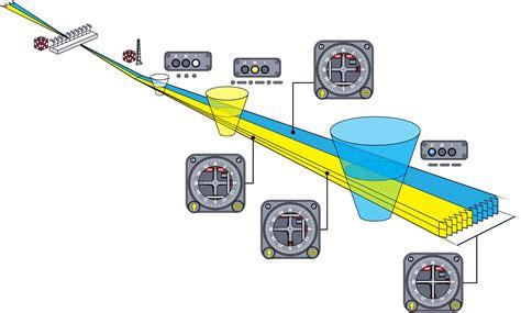
The Instrument Landing System (ILS) is a crucial tool for pilots, helping them land safely and accurately. It uses two radio beams to provide vertical and horizontal guidance during the landing approach. The localiser (LOC) helps with lateral positioning, while the glideslope (GS) ensures the correct vertical descent.
Marker beacons and high-intensity runway lights can also assist ILS operations. However, many marker beacons are now replaced by Distance Measuring Equipment (DME) or other navigational aids like VOR located at the airport. The LOC antennas are typically positioned at the runway’s end. They transmit two narrow beams that slightly angle to the left and right of the centerline, guiding pilots to the runway.
The GS antennas are usually found on the airfield as well, sending out two beams that indicate the correct vertical path. These beams intersect to define the GS indication. Normally, the glide-slope allows for a runway crossing height of about 50 feet, with a typical angle of 3 degrees. However, this angle can vary based on specific conditions, like terrain or noise restrictions.
If marker beacons are in use, they are placed at set distances from the runway. For instance, the Outer Marker is around 5 nautical miles from touchdown, while the Middle Marker is about 1 nautical mile away. A pilot cannot continue an approach unless the runway visual range (RVR) exceeds certain minimums. The ILS guidance is followed until reaching the decision height (DH), where pilots must have a clear visual reference to proceed. If not, a go-around is necessary.
There are special ILS categories that allow qualified pilots to operate under specific conditions. Category II allows for a DH as low as 100 feet and an RVR of at least 300 meters, while Category IIIA permits approaches with a DH below 100 feet and RVR no less than 200 meters. Category IIIB and IIIC take this further, allowing even lower thresholds, but Category IIIC is less commonly used due to post-landing maneuvering challenges.
For Categories II and III, specific aircraft equipment, pilot training, and airfield installations are required. For instance, runway holding points may be set back to prevent interference with signal transmission. Reliability is crucial; hence, secondary power supplies are necessary, and signals are continuously monitored. If any issues arise, the system shuts down, alerting the pilot to any malfunctions. Regular calibration checks ensure that ILS systems function correctly.
It’s essential to understand that only an ILS with both LOC and GS signals qualifies as a precision approach. If only the LOC is operational, it supports a Non-Precision Approach with higher minima. Pilots must adhere to strict boundaries when using ILS, defined by Full Scale Deflection (FSD) limits on their displays. If the deviation reaches FSD, it becomes challenging to assess the aircraft’s position. Therefore, pilots must cross-check their altitude against their distance to touchdown to confirm their position.
An issue known as false glideslope acquisition can occur, where secondary glide slopes appear above the primary one. This is due to the antenna’s radiation pattern and ground reflections. Capturing a false GS can lead to sudden changes in aircraft behavior, potentially resulting in an unstable approach. Ensuring proper altitude versus distance checks and following standard operating procedures can help mitigate these risks. Examples of incidents related to false GS acquisition have occurred, highlighting the importance of awareness and adherence to protocols.
")


 in Instrument Flight")
")
")
")
