Helicopters are among the most agile flying machines ever created, capable of vertical takeoff and landing (VTOL), hovering in place, and executing swift directional changes that would be impossible for fixed-wing aircraft. While their unmistakable rotor-blade silhouette is iconic in the skies, the mechanism behind their ability to change direction while airborne is far more nuanced and deeply rooted in aerodynamic engineering.
Unlike airplanes that rely on fixed wings and rudders, helicopters achieve maneuverability primarily through rotational dynamics. Understanding how helicopters change direction requires diving deep into the main rotor system, the swashplate assembly, and the different rotor configurations that make directional control possible.
The Central Role of the Swashplate in Directional Control
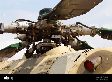
At the heart of a helicopter’s directional control lies the swashplate assembly, a mechanical device that enables the main rotor blades to tilt. It comprises two main parts: the stationary swashplate, which is fixed in place, and the rotating swashplate, which spins along with the rotor. The pilot controls the tilt of the swashplate via the cyclic stick, which changes the pitch of each rotor blade individually as it rotates.
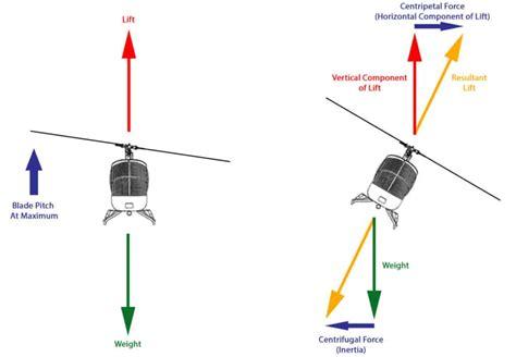
When a pilot moves the cyclic forward, the swashplate tilts accordingly, changing the angle of attack on each blade as it rotates. This results in more lift being produced on the aft part of the rotor disk and less on the forward part, causing the helicopter to tilt and move forward. By altering the tilt direction of the swashplate — forward, backward, or sideways — the pilot can direct the helicopter in any desired horizontal direction.
This is known as cyclic pitch control, and it allows the helicopter to translate its movement laterally. Collective pitch, on the other hand, changes the pitch angle of all rotor blades equally and is used for ascending or descending.
Countering Torque with the Tail Rotor
In helicopters featuring the traditional main and tail rotor configuration, the tail rotor plays a critical role in directional control, particularly when it comes to yawing — turning left or right around the vertical axis.
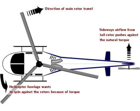
As the main rotor spins to produce lift, it generates a reactive torque that would otherwise spin the helicopter’s fuselage in the opposite direction. The tail rotor counteracts this torque by generating horizontal thrust. The pilot controls the tail rotor’s thrust using anti-torque pedals, adjusting the amount of side thrust and thus rotating the helicopter’s nose left or right.
Through a combination of cyclic input (to change direction) and tail rotor input (to maintain or change yaw), a pilot can execute coordinated turns, hover turns, and directional transitions with high precision.
Rotorcraft Evolution: A Century of Directional Refinement
The ability of helicopters to perform agile aerial maneuvers did not emerge overnight. Early experiments in rotorcraft in the 1910s laid the foundation for more practical designs. One of the first successful designs was by Jacob Ellehammer, who developed a coaxial rotor concept that could hover.
Throughout the 1920s and 1930s, autogyros helped refine the concept of controlled rotorcraft flight, leading to the post-WWII emergence of operational helicopters like the Bell 47, one of the most iconic helicopters ever built. These developments hinged on understanding how rotor systems could be manipulated to provide omnidirectional control — a revolutionary departure from the limitations of fixed-wing flight.
With each advancement, engineers improved the swashplate mechanism, refined tail rotor design, and explored new rotor configurations that eliminated the need for a tail rotor altogether.
Alternative Rotor Configurations That Eliminate Tail Rotors
Not all helicopters use the traditional single main rotor and tail rotor layout. In fact, rotorcraft designers have developed innovative configurations that achieve directional control without requiring a tail rotor at all. These designs rely on counter-rotating rotors to neutralize torque and introduce new methods for controlling yaw and pitch.
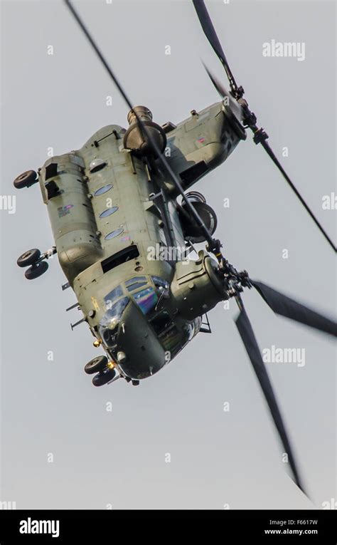
Tandem Rotor Configuration (e.g., Boeing CH-47 Chinook)
In this layout, the helicopter has two large horizontal rotors—one mounted on the front and the other on the rear. Both rotors spin in opposite directions, canceling out each other’s torque. Directional changes are achieved by varying the lift on one rotor versus the other. For instance, increasing lift on the front rotor and decreasing it on the rear causes the helicopter to pitch backward.
Yaw is controlled by differential cyclic pitch — applying opposite cyclic inputs to each rotor, which produces a yaw moment. The Boeing CH-47F Chinook, used extensively in military logistics, exemplifies this configuration.
Intermeshing Rotor Configuration (e.g., Kaman HH-43 Huskie)
Also known as a synchropter, this system uses two rotors mounted on separate, slightly inclined masts, with their rotor disks intermeshing without colliding. The counter-rotation cancels torque naturally. Yaw and pitch are controlled via differential cyclic inputs.
This design provides excellent stability and high lifting capacity in a compact frame. The Kaman HH-43 Huskie, used during the Vietnam War, employed this unique layout effectively.
Coaxial Rotor Configuration (e.g., Kamov Ka-31)
Coaxial helicopters use two rotors mounted on the same axis but spinning in opposite directions. This layout also cancels torque without requiring a tail rotor. The Ka-31, developed in Russia, is one of the best-known coaxial rotor helicopters. To change yaw, the flight control system modulates the pitch of the upper and lower rotor blades differently, creating a yawing moment.
This configuration provides superior agility, especially in confined spaces, and better lift efficiency in high-speed scenarios.
Side-by-Side Rotor Configuration (e.g., Mil V-12)
The rarest of the configurations, side-by-side rotor helicopters feature two massive rotors mounted on short wings extending from either side of the fuselage. Each rotor rotates in the opposite direction, cancelling torque. Yaw is controlled by applying different thrust levels to each rotor, while pitch and roll are controlled by synchronizing their cyclic inputs.
The Mil V-12, the world’s largest helicopter, remains a towering example of this rare but powerful configuration.
Coordinated Control: Mastering Multidimensional Flight
Regardless of the rotor configuration, helicopter pilots must simultaneously manage three key inputs:
- Cyclic control (directional movement: forward, back, left, right)
- Collective control (altitude: up or down)
- Anti-torque or yaw control (rotation about the vertical axis)
Together, these controls allow for precision navigation, particularly in challenging operational environments such as urban landscapes, mountainous terrain, and battlefield zones.
Changing direction midair is not just a matter of pointing the nose and gunning the throttle. It involves carefully modulating lift and thrust vectors through constant adjustments to pitch and angle of attack. This precise control grants helicopters unmatched versatility, allowing them to hover, pivot in place, or dart sideways — all feats impossible for conventional aircraft.
Advanced Systems: Fly-by-Wire and Autopilot Enhancements
Modern helicopters increasingly incorporate fly-by-wire systems, where computer-assisted flight controls translate pilot input into optimized control surface movements. This improves precision and stability, reducing pilot workload and enhancing safety.
Some military and commercial rotorcraft are equipped with autopilot systems that can manage hover stability, programmed turns, and complex waypoints. These systems rely on sensors and real-time data to adjust swashplate angles and rotor pitch without manual input.
These technologies continue to push the boundaries of what helicopters can do, allowing for safer flight in inclement weather, automated rescue missions, and even the development of unmanned aerial rotorcraft.
Conclusion: Controlled Chaos in the Skies
Helicopters are deceptively complex machines that defy traditional aerodynamic principles with controlled chaos. From the elegance of the swashplate mechanism to the brute force cancellation of torque by counter-rotating rotors, every directional change midair is a finely orchestrated ballet of physics and engineering.
Whether equipped with a tail rotor or designed around exotic rotor configurations, helicopters continue to be the go-to aircraft where agility, precision, and vertical flight are paramount. Understanding how they change direction reveals not just the mechanics of movement, but the culmination of over a century of innovation — making them one of humanity’s most impressive technological achievements in the sky.


")
")


