A Hyperbolic Navigation System is designed to create hyperbolic lines of position. This is achieved by measuring the differences in time or phase between radio signals from two or more synchronized transmitters. When we assume that the speed of these signals remains constant in a specific area, we can calculate the distance between a transmitter and a receiver based on the time it takes for the signal to travel.
In theory, if we measure the reception time of multiple signals, we could determine a precise location. However, this requires the receiver to know exactly when each signal was sent. To do this, both the transmitter and receiver need very accurate clocks that are perfectly synchronized. Unfortunately, technical limitations and high costs make this absolute timing approach impractical for mobile receivers. Instead, we rely on differential timing methods, leading to the development of Hyperbolic Navigation Systems.
In a differential timing system, the receiver does not need to be synchronized with the transmitters. It only requires signals from a single station, a series of stations, or the entire system to be synchronized. This synchronization can be achieved through various methods, such as hard-wiring the transmitter locations, using a master-slave setup, or employing highly precise clocks at each transmitter site. The receiver doesn’t need to know the exact time a signal was sent; it only needs to recognize that signals from two stations were transmitted simultaneously. By measuring the time difference between receiving these signals, the receiver can be located along a specific Line of Position (LOP) defined by that time differential.
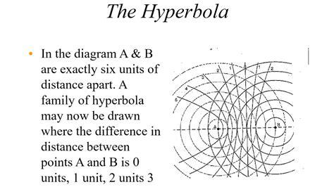
This means that a single measurement gives a range of possible locations rather than pinpointing an exact spot. When we measure the timing difference from a second transmitter pair, we get another LOP, and where these two lines intersect indicates the receiver’s location. A helpful YouTube video by Cristhian Timoté illustrates how hyperbolic Lines of Position are formed between two synchronized transmitters. The video shows two radio transmitters with concentric circles representing the distances traveled by their signals. The points where these circles intersect create a series of hyperbolae, with the straight line perpendicular to the baseline between the transmitters marking all points with zero time of reception differential. Each of the other hyperbolic curves corresponds to a specific time differential. Therefore, to accurately identify a receiver’s position, we need a second LOP from another transmitter pair or navigational tool.

")
")
")
")

")

