In the world of aviation, the attitude indicator (AI) stands as one of the most critical instruments in a pilot’s arsenal. Also known as the gyro horizon or artificial horizon, the attitude indicator is a primary flight tool that precisely displays the aircraft’s orientation relative to the Earth’s horizon. Without it, safe flight under instrument meteorological conditions would be nearly impossible.
The AI provides an instantaneous visual representation of pitch (nose up or down) and bank (left or right tilt), enabling pilots to maintain stable flight even when the outside view is obscured. Its importance in instrument flight rules (IFR) operations cannot be overstated, and its design and operation have evolved significantly over the years.
The Evolution of Artificial Horizons
Before aviation even took off, navigators devised ways to determine orientation without a clear horizon. Early versions of an artificial horizon were used in celestial navigation, relying on devices like bubble levels attached to sextants. The concept of a gyroscope-based horizon was first proposed in the 1740s by innovators such as John Serson, who designed primitive gyroscopic devices to simulate an artificial horizon for seafaring navigators.
As aviation matured, especially throughout the 20th century, the necessity for a stable, reliable attitude reference led to the adoption of gyroscopic attitude indicators in aircraft. Some early versions even utilized liquid mercury for stability—a fascinating discovery confirmed by remnants recovered from the wreck of HMS Erebus in the 2010s.
The transition from rudimentary designs to precise, mechanically sophisticated instruments revolutionized flight, enabling safer, longer, and more complex operations under diverse conditions.
Core Components and Display Features
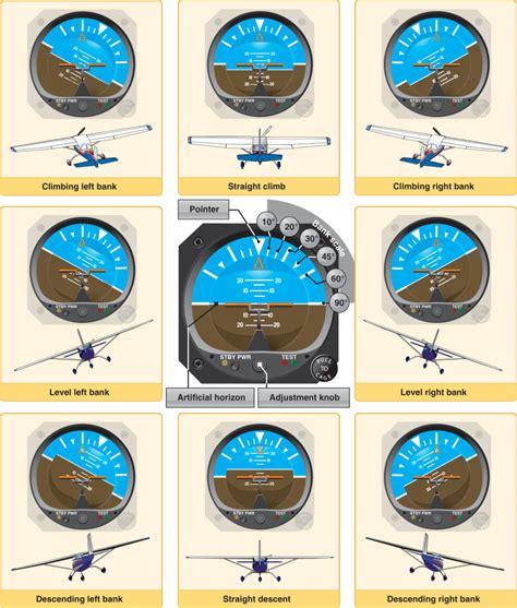
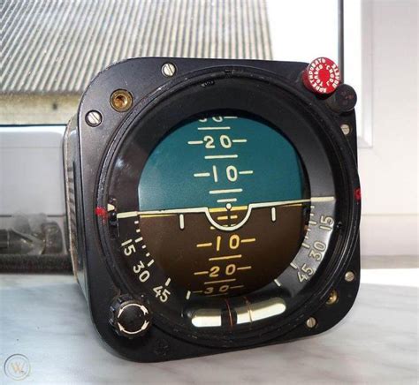
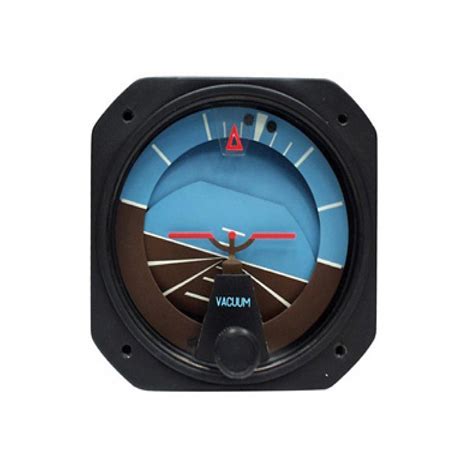
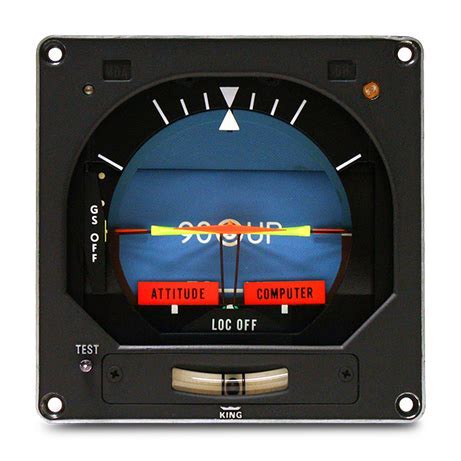
The attitude indicator comprises several critical visual elements, each meticulously designed for intuitive interpretation under the demanding environment of flight. At its heart lies a miniature aircraft symbol, fixed against a moving background that represents the sky and ground. The upper hemisphere is rendered in blue, symbolizing the sky, while the lower is brown, depicting the Earth.
Reference lines mark various degrees of pitch above and below the horizon, while the bank scale—positioned along the upper circumference—indicates degrees of roll to the left or right. Pilots can adjust the alignment using a knob to match their specific line of sight with the artificial horizon.
In Western-style indicators, the background tilts with the aircraft’s bank, keeping the aircraft symbol fixed. Conversely, many Russian-designed instruments operate differently: the aircraft symbol itself moves laterally against a static background, only the pitch causing background motion. Though a hybrid between these designs was proposed for improved intuitiveness, it never gained widespread adoption.
Operational Mechanics: The Role of the Gyroscope
At the mechanical heart of the AI lies the gyroscope, spinning at extraordinary speeds to resist changes in orientation. Powered either electrically or pneumatically, via a vacuum pump or venturi system, the gyro maintains a vertical alignment relative to gravity.
In a typical vacuum-powered system, air accelerates through a venturi, creating a low-pressure zone that draws air through the gyro housing, spinning the rotor. Mounted within a double gimbal, the gyro stays vertically stable while allowing the aircraft to pitch and roll freely.
To maintain alignment over time, the instrument employs erection mechanisms. For vacuum gyros, tiny pendulums attached to the rotor casing regulate airflow through small holes, correcting orientation errors by applying minute forces toward verticality. Electric gyros, meanwhile, use similar mechanical or electronic corrections tailored to the system’s design.
It is important to note that start-up time is required for the system to stabilize. A gyroscope will not immediately present a perfectly level horizon upon engine ignition; it may take several minutes to self-erect fully.
Common Errors and Limitations
Although attitude indicators are renowned for their reliability, certain limitations and errors do exist. Rapid accelerations or decelerations can momentarily create false indications: the aircraft may show a slight nose-up during acceleration and nose-down during deceleration.
Extended turns or prolonged flight over long distances (where the Earth’s curvature becomes a factor) can induce slight discrepancies in pitch and bank readings. However, these inherent errors are typically minor and self-correct within a short duration of stable, straight-and-level flight.
Older generation instruments faced an additional challenge—tumbling. If subjected to pitch attitudes exceeding approximately 60° or roll angles beyond 100°, the gyroscope could tumble, causing a loss of reference. To counteract this, a caging mechanism was included to lock the gyro during extreme maneuvers. Modern attitude indicators, particularly those incorporated into glass cockpits, have eliminated the tumbling issue through enhanced gyroscopic designs and sensor technologies.
Advancements: From Aircraft to Spacecraft
Not confined to terrestrial aviation, the attitude indicator found an essential role in the realm of spaceflight. In spacecraft such as Apollo missions, a variant known as the Flight Director Attitude Indicator (FDAI) was pivotal.
The FDAI, coupled with an Inertial Measurement Unit (IMU), provided astronauts with crucial pitch, yaw, and roll information relative to a fixed-space inertial reference. This innovation enabled precise navigation, attitude control, and orbital maneuvering even in the vastness of space where conventional horizons do not exist.
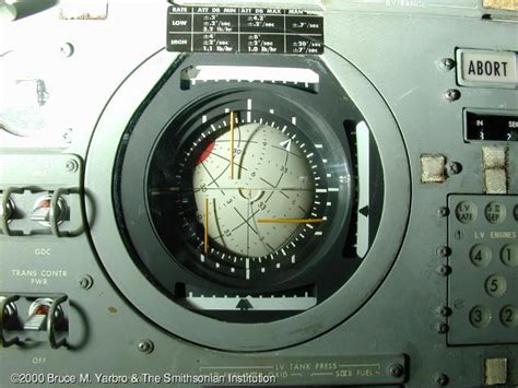
NASA engineers configured the FDAI to reference not only Earth but also celestial markers, facilitating detailed communication and coordination between spacecraft crews and mission control.
Modern Innovations: AHRS and Digital Systems
The evolution from mechanical to solid-state technology has dramatically reshaped the landscape of attitude indicators. The advent of Attitude and Heading Reference Systems (AHRS) represents a leap in accuracy, reliability, and integration.
AHRS utilize ring laser gyroscopes, rate gyros, magnetometers, and advanced low-cost inertial sensors. Rather than relying on a mechanical spinning mass, these systems electronically compute the aircraft’s attitude, enhancing resilience to mechanical failures and environmental disturbances.
In modern glass cockpit configurations, AHRS data feeds multiple displays, ensuring that primary flight displays (PFDs) remain synchronized. If the primary system fails, aircraft are often equipped with a standby attitude indicator, typically located centrally on the instrument panel alongside essential backup instruments like the airspeed indicator and altimeter.
It is crucial to recognize, however, that even these standby instruments may be electrically driven. Consequently, complete electrical failure can eventually render them nonfunctional unless independently powered.
The Attitude Direction Indicator: A Step Further
Building upon the conventional AI, the Attitude Direction Indicator (ADI) or Flight Director Indicator (FDI) integrates flight director systems into the display.
The ADI superimposes steering cues onto the horizon representation. Typically shaped like a yellow “V”, these steering bars indicate the desired flight path relative to the aircraft’s current attitude. Pilots maneuver the aircraft so that the miniature airplane symbol aligns within the “V”, allowing for precise flight path control without the need to interpret separate navigation instruments.
This integration significantly reduces pilot workload, especially during complex instrument approaches, climbs, or descents governed by instrument landing systems (ILS) or area navigation (RNAV) procedures.
Conclusion: The Unwavering Value of the Attitude Indicator
The attitude indicator remains a cornerstone of aviation safety, from the earliest open-cockpit biplanes to today’s advanced airliners and spacecraft. Its evolution from simple mechanical devices to sophisticated digital systems underscores its irreplaceable role in navigating both the skies and the cosmos.
Whether powered by spinning gyros or solid-state electronics, the AI’s unwavering horizon offers pilots a crucial lifeline, maintaining situational awareness when visibility outside the cockpit is nonexistent. Understanding its operation, limitations, and technological advancements ensures that pilots continue to fly safely and confidently, even when the real horizon fades from view.


")


")

")