Hydraulic systems form the lifeblood of modern industrial machinery, aerospace operations, and heavy-duty mechanical frameworks. By transmitting power through pressurized fluid, these systems accomplish tasks that would be unmanageable using purely mechanical or electrical means. As specialists in the field, we emphasize the critical importance of understanding the various types of hydraulic systems—each with its own architecture, performance characteristics, and application environment. A well-informed approach to hydraulic technology not only boosts operational efficiency but also minimizes system faults, such as pump leakage, gas intrusion, valve degradation, and oil aeration.
What Is a Hydraulic System?
A hydraulic system is a power transmission mechanism that employs incompressible fluid—typically oil—to convert mechanical input into highly controllable and repeatable force. The core concept revolves around Pascal’s Law, which states that pressure applied at any point in a confined fluid is transmitted equally in all directions. This principle allows hydraulic systems to generate immense force from compact actuators, making them indispensable in environments where space is limited but power demand is high.
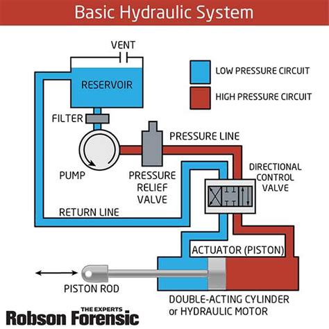
Unlike pneumatic systems that use compressible air, hydraulic systems offer precise control and smoother motion, making them ideal for applications in manufacturing plants, aerospace control surfaces, construction equipment, and robotic actuation. These systems consist of reservoirs, pumps, valves, actuators, and filters, each playing a unique role in facilitating fluid movement and force transfer.
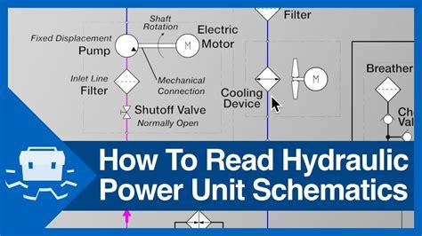
1. Hydraulic Pump Systems
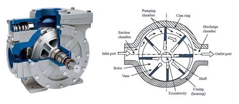
Hydraulic pump systems serve as the beating heart of any hydraulic framework. Their function is to convert mechanical energy (from electric motors or combustion engines) into hydraulic energy by forcing fluid into pressurized lines. There are several pump types, each suited to specific performance needs:
- Gear Pumps: These are fixed displacement pumps that deliver a consistent volume of fluid per rotation. Ideal for low-pressure systems, they are simple, reliable, and cost-effective.
- Fixed Displacement Piston Pumps: Used where flow rates need to be predictable and uniform. They offer higher pressure than gear pumps but sacrifice variability.
- Variable Displacement Piston Pumps: Predominantly used in aerospace and mobile machinery, these pumps can adjust their fluid output based on system demand, improving efficiency and control.
In aviation and industrial robotics, variable displacement technology is prized for enabling adaptive control, reducing energy consumption during low-load cycles.
2. Hydraulic Motors and Cylinders
Where pumps drive fluid, hydraulic motors and cylinders perform mechanical work. These components translate fluid pressure into rotational or linear motion, depending on the actuator type:
- Hydraulic Motors: Operate like reverse pumps. They convert pressurized fluid into torque and angular displacement. Common motor variants include vane motors, radial piston motors, and gear motors, each tailored for specific torque-to-speed ratios.
- Hydraulic Cylinders: Often referred to as linear actuators, these push or pull loads in a straight line. Found in excavators, press machines, and aerospace landing gear, they deliver controlled, high-force movement.
A system can integrate multiple actuators in parallel, allowing a centralized pump to power a complex mechanical choreography.
3. Aviation Hydraulic Systems
The aviation sector demands precision, redundancy, and reliability, making hydraulic systems the default for flight control surfaces, landing gear, and braking systems. Aircraft hydraulic systems follow a closed-loop or open-loop architecture and include:
- Reservoirs that hold the fluid
- Main and auxiliary pumps for pressurization
- Manifolds and valves to control direction and pressure
- Actuators for motion
These systems continuously circulate hydraulic fluid from reservoir to actuator and back, enabling real-time adjustments to flight dynamics. In commercial and military aircraft, triple-redundant hydraulic loops ensure fail-safe operation.
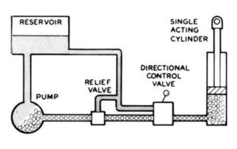
4. Open-Center Hydraulic Systems
In an open-center hydraulic system, fluid circulates through the system without creating pressure when the actuators are idle. This configuration is energy efficient when no active movement is required. Key characteristics include:
- Continuous fluid flow through the control valve to the reservoir
- No pressure buildup unless actuated
- Directional control valves that open or close based on operator input
- Less heat generation due to lack of back pressure
These systems are common in agricultural tractors, material handling equipment, and low-duty cycle machinery. The fluid returns to the open reservoir, often with air bubble separation zones, ensuring contaminant-free re-circulation.
5. Closed-Loop Hydraulic Systems
Closed-loop systems, also called hydrostatic systems, are more complex and suited for high-demand applications requiring fast and accurate actuation. In these systems:
- The pump and actuator form a self-contained circuit, excluding the reservoir from the primary fluid path
- A charge pump (or feed pump) maintains system pressure, compensating for minor fluid losses
- The system is pressurized continuously, allowing rapid response
Due to their high-pressure capacity and compact size, closed-loop designs are preferred in precision CNC machinery, high-performance vehicles, and mobile hydraulic drives like bulldozers and cranes.
Closed-loop systems reduce fluid exposure to air, lowering oxidation and preventing oil aeration, one of the top fault conditions in hydraulic operations.
Fault Scenarios in Hydraulic Systems
Even the most sophisticated hydraulic setup can suffer from critical issues if not properly maintained. Among the most common fault scenarios are:
- Pump Leakage: Usually caused by worn seals, thermal damage, or cavitation. Leads to pressure drop and performance loss.
- Gas Leakage (Aeration): Air trapped in the fluid creates foam, reducing fluid compressibility and causing erratic actuator movement.
- Valve Switching Degradation: Contaminants or wear can affect spool valves’ ability to redirect flow efficiently.
- Oil Aeration: Often confused with cavitation, aeration involves actual air pockets disrupting flow and increasing thermal stress.
Preventive maintenance using advanced diagnostic sensors, fluid monitoring, and regular valve inspection can substantially reduce the frequency and impact of these faults.
Hydraulic Systems in Industrial Application
Industries rely on tailored hydraulic architectures to match their operational footprint and energy demands. In manufacturing, hydraulic presses and injection molding machines utilize high-pressure closed-loop systems for consistent performance. Construction machinery like backhoes and trenchers use open-center systems for modular control. Meanwhile, wind turbines increasingly depend on hydraulic pitch systems for blade angle regulation, ensuring energy output aligns with wind speed variations.
Conclusion: Choosing the Right Hydraulic System
Selecting the correct hydraulic configuration is not just a matter of performance, but one of safety, energy efficiency, and long-term asset viability. Open systems offer simplicity and affordability, whereas closed systems bring precision and robustness. Aviation-grade systems must meet stringent redundancy standards, while industrial designs balance cost with responsiveness. Ultimately, understanding these hydraulic variants empowers operators, engineers, and stakeholders to optimize equipment for maximum uptime, output, and durability.
Frequently Asked Questions
What is the difference between an open and closed hydraulic system?
An open hydraulic system allows fluid to flow freely back to the reservoir when not in use, reducing pressure and heat generation. A closed system recirculates fluid between the actuator and pump, providing continuous pressure for fast and accurate actuation, with no direct return to the reservoir.
Why do hydraulic systems suffer from aeration?
Aeration occurs when air is introduced into the hydraulic fluid, often through leaks or improper maintenance. This leads to foam formation, reducing fluid effectiveness, increasing compressibility, and potentially damaging components through irregular motion and overheating.
Which hydraulic pump is best for aircraft?
Aircraft commonly use variable displacement piston pumps due to their ability to adjust flow rate based on system demand. This flexibility allows for precise control, energy savings, and enhanced system safety, especially in flight-critical scenarios.


