Defining Load Factor and Its Role in Aerodynamics
In aviation dynamics, load factor is one of the most critical concepts underpinning aircraft performance, flight safety, and structural integrity. It is mathematically expressed as:
( N = \frac{L}{W} )
Where:
-
(N) = Load Factor (dimensionless)
-
(L) = Lift force generated by the wings
-
(W) = Weight of the aircraft (mass × gravitational acceleration)
This ratio defines how many times the aircraft’s weight is being supported by aerodynamic lift. In straight and level unaccelerated flight, this value equals 1, meaning lift exactly counteracts weight. However, in maneuvers—especially turns and pull-ups—the value can increase significantly.
Load factor plays a pivotal role in structural engineering limits, pilot control inputs, and aerodynamic certification, with higher values indicating more stress being applied to both the aircraft structure and occupants.
Normal Acceleration: The Z-Axis Component
The term normal acceleration (nz) refers to the acceleration measured along the aircraft’s body Z-axis, which is perpendicular to the wings and generally points downward through the aircraft. This acceleration is a vector quantity, usually measured in g units (where 1g = 9.81 m/s²). It is calculated using onboard accelerometers and represents what the pilot and passengers physically feel.
While load factor and normal acceleration often coincide in magnitude under ideal conditions, they are not equivalent:
-
Load Factor is dimensionless.
-
Normal Acceleration has units of acceleration (m/s²).
This difference leads to frequent confusion in aviation training and operational assessments.
Key Differences: Load Factor vs Normal Acceleration
The confusion arises because under coordinated flight, especially in level turns, the numerical values of load factor and normal acceleration can appear identical. But conceptually and physically, they remain distinct due to differing definitions and unit bases.
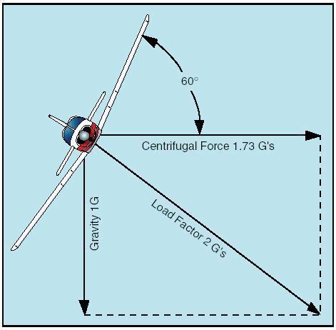
In straight and level flight, where the only significant forces are lift and weight, the aircraft’s net vertical acceleration is zero, but the normal acceleration (nz) equals 1g due to the upward lift balancing gravity. In a level coordinated turn, the lift vector tilts and increases in magnitude to maintain altitude, producing a higher load factor, e.g., 2g in a 60° banked turn.
However, in uncoordinated flight, such as during a slip or skid, or when strong side forces act on the aircraft, normal acceleration may include other components not directly derived from lift alone.
Force Components and Flight Dynamics
Analyzing normal acceleration requires an understanding of all aerodynamic forces acting on the aircraft:
-
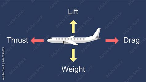
Lift: Always acts perpendicular to the relative airflow.
-
Weight: Always acts vertically downwards in the Earth reference frame.
-
Thrust and Drag: Affect acceleration in the forward and aft directions but do not significantly alter normal acceleration unless the aircraft is in extreme pitch or high-angle climb or descent.
Thrust and drag generally align with the aircraft’s longitudinal axis and rarely affect Z-axis acceleration significantly during steady flight. But in certain scenarios—like aerobatic maneuvers or non-standard climbs—they can introduce meaningful components.
Calculating Load Factor in Dynamic Maneuvers
In most practical scenarios, we simplify calculations by assuming:
( N = nz )
This approximation is valid under coordinated flight, level turns, and predictable control inputs. In real-world operations, aircraft often operate near these conditions, enabling this simplification for flight manual data and pilot reference.
However, in advanced flight dynamics modeling or when analyzing flight data recorders, this assumption may not hold. Engineers must account for the vector decomposition of forces, adjusting for bank angles, pitch, and yaw to derive the precise normal acceleration.
Implications of Load Factor on Structural Limits
Aircraft are certified for specific positive and negative load limits, often listed in the aircraft flight manual (AFM). Exceeding these values risks structural deformation or catastrophic failure. Common examples include:
-
Transport category aircraft: +2.5g to -1.0g
-
Utility category: +4.4g
-
Acrobatic category: +6.0g to -3.0g
These limits are calculated considering worst-case aerodynamic and mass distribution scenarios. Understanding the load factor formula is vital for maintaining safe operations, particularly in aggressive flight profiles.
The Physics of ‘Felt’ Acceleration
A pilot’s felt acceleration corresponds to the sum of non-gravitational forces acting on the aircraft. When you feel yourself pressed into your seat during a pull-up maneuver or turn, that’s a manifestation of increased normal acceleration. It is distinct from the net acceleration of the aircraft, which includes gravity.
This means:
-
An aircraft in free fall experiences zero g felt acceleration despite falling at 9.81 m/s².
-
An aircraft pulling out of a dive may feel 3g, even though the net acceleration is less due to gravity acting downward.
Felt acceleration thus provides the real-time physiological and structural stress measurement, making it crucial in both pilot situational awareness and airframe fatigue tracking.
Typical Flight Scenarios and Their Load Factor Impacts
To fully grasp the implications of the load factor formula, we must examine several real-world flight conditions:
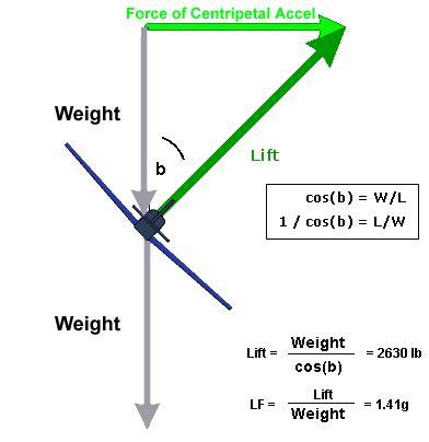
Coordinated Turn
In a 60° banked turn, the lift vector must increase to counteract both gravity and centrifugal force. The required lift becomes:
( L = \frac{W}{\cos \theta} )
Where (\theta) is the bank angle. This results in a load factor of:
( N = \frac{1}{\cos \theta} = 2 ) for (\theta = 60°)
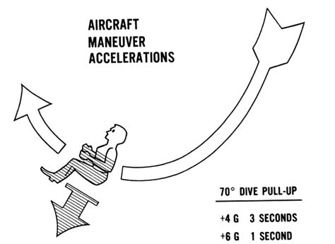
Vertical Pull-Up
During a rapid transition from a dive to level flight, the aircraft’s lift must not only counteract weight but also provide the centripetal force for the curved path, significantly increasing the load factor.
Climb or Descent
In steady-state climbs or descents, assuming constant velocity, the load factor remains near 1g, as lift still balances the vertical component of weight. However, any pitch changes that involve acceleration will cause transient increases in nz.
Instrumentation and Measurement Tools
Accelerometers, flight data recorders, and strain gauges onboard aircraft allow precise monitoring of normal acceleration. These values are crucial for:
-
Post-flight analysis
-
Pilot training reviews
-
Structural maintenance tracking
G-meters provide direct pilot feedback on in-flight acceleration. Pilots in high-performance aircraft use this data to ensure they stay within safe operational limits.

Conclusion: A Nuanced but Critical Distinction
While load factor and normal acceleration are closely related, their conceptual definitions, units, and application contexts vary significantly. The formula ( N = \frac{L}{W} ) offers a simplified yet powerful model to evaluate aerodynamic stress, but understanding the vector mechanics and perceived acceleration is essential in modern aviation.
For pilots, engineers, and aerospace scientists, the correct interpretation of these metrics informs not just safety, but also the performance envelope, design constraints, and human factors influencing flight.
Frequently Asked Questions
Is the load factor always equal to the normal acceleration?
No, although they may have similar values during coordinated flight, they differ conceptually. Load factor is a dimensionless ratio of lift to weight, while normal acceleration is a measured acceleration (in g) acting along the body Z-axis.
What causes a high load factor in an aircraft?
Turning maneuvers, pull-ups, and gust loads are common causes. Increased bank angles require greater lift to maintain altitude, thereby increasing the load factor. Structural design must accommodate these high-stress events.
Why is understanding load factor important for pilots?
Pilots must avoid exceeding the aircraft’s structural limits, which are defined in terms of load factor. This ensures flight safety, reduces fatigue accumulation, and prevents mid-air structural failure.


